Reactors
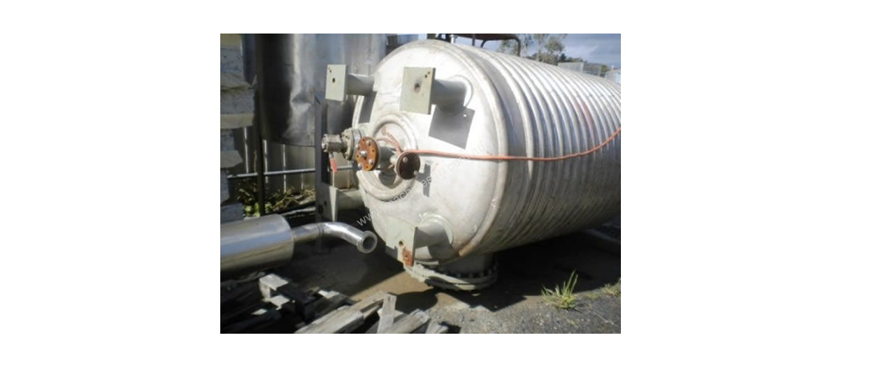
Reactors
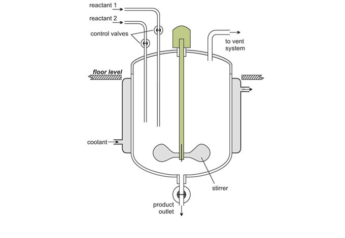
Batch reactors
Batch reactors are used for most of the reactions carried out in a laboratory. The reactants are placed in a test-tube, flask or beaker. They are mixed together, often heated for the reaction to take place and are then cooled. The products are poured out and, if necessary, purified.
This procedure is also carried out in industry, the key difference being one of size of reactor and the quantities of reactants.
Following reaction, the reactor is cleaned ready for another batch of reactants to be added.
Batch reactors are usually used when a company wants to produce a range of products involving different reactants and reactor conditions. They can then use the same equipment for these reactions.
Examples of processes that use batch reactors include the manufacture of colorants and margarine.
Continuous reactors
An alternative to a batch process is to feed the reactants continuously into the reactor at one point, allow the reaction to take place and withdraw the products at another point. There must be an equal flow rate of reactants and products. Whilecontinuous reactors are rarely used in the laboratory, a water-softener canberegarded as an example of a continuous process. Hard water from the mains is passed through a tube containing an ion-exchange resin. Reaction occurs down the tube and soft water pours out at the exit.
Continuous reactors are normally installed when large quantities of a chemical are being produced. It is important that the reactor can operate for several months without a shutdown.
The residence time in the reactor is controlled by the feed rate of reactants to the reactor. For example, if a reactor has a volume of 20 m3 and the feed rate of reactants is 40 m3 h-1 the residence time is 20 m3 /40 m3 h-1 = 0.5 h. It is simple to control accurately the flow rate of reactants. The volume is fixed and therefore the residence time in the reactor is also well controlled.
The product tends to be of a more consistent quality from a continuous reactor because the reaction parameters (e.g. residence time, temperature and pressure) are better controlled than in batch operations.
They also produce less waste and require much lower storage of both raw materials and products resulting in a more efficient operation. Capital costs per tonne of product produced are consequently lower. The main disadvantage is their lack of flexibility as once the reactor has been built it is only in rare cases that it can be used to perform a different chemical reaction.
Types of continuous reactors
Industry uses several types of continuous reactors.
(a) Tubular reactors
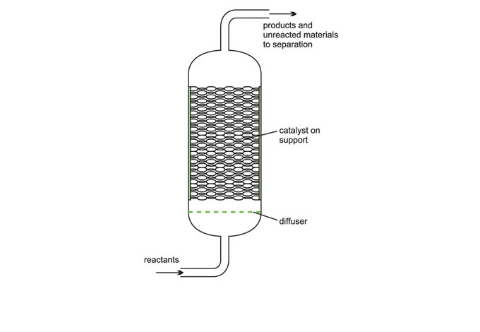
In a tubular reactor, fluids (gases and/or liquids) flow through it at high velocities. As the reactants flow, for example along a heated pipe, they are converted to products (Figure 4). At these high velocities, the products are unable to diffuse back and there is little or no back mixing. The conditions are referred to as plug flow. This reduces the occurrence of side reactions and increases the yield of the desired product.
With a constant flow rate, the conditions at any one point remain constant with time and changes in time of the reaction are measured in terms of the position along the length of the tube.
The reaction rate is faster at the pipe inlet because the concentration of reactants is at its highest and the reaction rate reduces as the reactants flow through the pipe due to the decrease in concentration of the reactant.
BELT DISCHARGE
The LOVELY PROJECT AND ENGINEERING. Belt discharge RVDF carrying a fabric that is removed, passed over rollers, washed, and returned to the drum. A special aligning device keeps the medium wrinkle-free and in proper line during its travel. Thin cakes of difficult solids which may be slightly soluble are good applications. When acceptable, a sluice discharge makes cakes as thin as 1.5 to 2 mm (about gin) feasible.
STRING DISCHARGE
The LOVELY PROJECT AND ENGINEERING. String discharge RVDF system of endless strings or wires spaced about 13 mm (0.5 in) apart pass around the filter drum but are separated tangentially from the drum at the point of cake discharge, lifting the cake off as they leave contact with the drum.
The strings return to the drum surface guided by two rollers, the cake separating from the strings as they pass over the rollers. If it has the required body, a thinner cake (5 mm) than can be handled by drum filters is feasible, allowing more difficult materials to be filtered. This is done at the expense of greater dead area on the drum. Success depends on the ability of the cake to be removed with the strings and must be determined experimentally.
Applications are mainly in the starch and pharmaceutical industries, with some in the metallurgical field.
ROLLER DISCHARGE
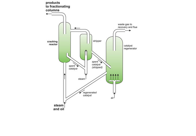
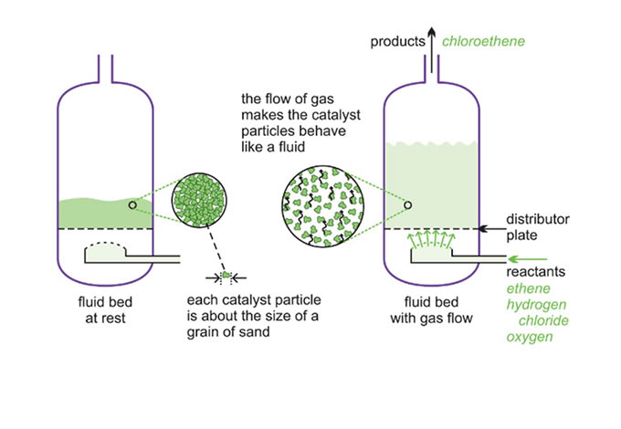
A silica-alumina catalyst is used but fine particles of carbon are rapidly deposited on its surface and the catalyst quickly becomes ineffective. The catalyst, still in the form of a fluid, is regenerated as it passes into a second vessel where it is heated strongly in air (sometimes with added oxygen) burn off the carbon (Figure 7) and then returned into the reaction zone and mixed with gas oil.
1 Fractionating column to remove and recover the butanes <br>
2 The catalyst regenerator <br>
3 Fractionating column to remove and recover ethane <br>
By kind permission of ExxonMobil and Pail Carter Photography.
These reactors are larger than fixed bed reactors and are more expensive to construct. However, it is easier to control the conditions and the process is more efficient.
